
Le stampanti 3D sono sempre più diffuse nel mondo dei makers tuttavia non smettono mai di stupirmi come il progetto: 3D Printing Brushless DC Motor
in cui Patrick Eells ha realizzato un video sulla realizzazione di un motore brushless interamente stampato con una stampate 3D Makerbot in fasi successive.
Uno dei limiti della stampa FDM, mi hanno spiegato, è la difficoltà di interrompere un flusso di stampa per riprendere dal punto di interruzione a causa del metodo di fusione del filamento che rischia fortemente di non legare con la parte già stampata.
Questo tipo di difficoltà non sembra aver preoccupato Patrick che ha realizzato un video del progetto (vedi sotto).
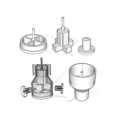
I file 3D del progetto 3D Printing Brushless DC Motor
L’autore ha pubblicato tutti i disegni in formato .stl per consentirti di riprodurre il progetto con la tua makerbot, li trovi qui.
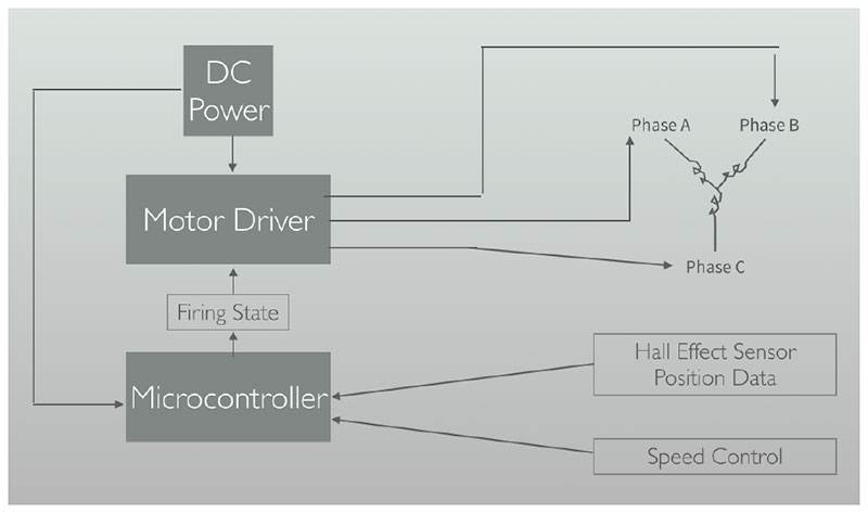
Ma non si è limitato solo ai disegni ed ha rilasciato una relazione, in formato PDF che trovi nel link sopra, in cui ti spiega passo passo come realizzare il 3D Printing Brushless DC Motor dalla stampa delle singole parti fino allo sketch che gli consente di far funzionare il motore, senza tralasciare il principio di funzionamento e gli studi che ha condotto prima di realizzare il progetto:
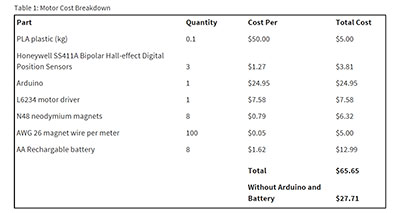
ed i costi del 3D Printing Brushless DC Motor:
Lo sketch del 3D Printing Brushless DC Motor
Patrick ha pubblicato anche lo sketch che puoi utilizzare per controllare il 3D Printing Brushless DC Motor e con qualche accorgimento probabilmente anche altri motori brushless con arduino:
/*
 * BLDC_congroller 1.0
 * by Patrick Eells
 * based on instructable by David Glaser
 *
 * Designed to work with the ST L6234 3-Phase Motor Driver.
 * Runs a 3D printed 3phase motor counterclockwise.
 * Motor speed is controlled by a single potentiometer.
 * Motor position is determined with three Hall-Effect sensors.
 * The Arduino receives outputs from 3 hall sensors (pins 2,3,4)
 * and converts their combination to 6 different commutation steps.
 * PWM outputs on pins 9,10,11, at 32 kHz (corresponding to
 * EN 1,2,3 respectively. 3 DO on pins 5,6,7 (IN 1,2,3).
 * Analog in 0 is connected to a potentiometer to change the
 * PWM duty and switch motoring on and off.
 * 0-127: off
 * 128-1023: on
 * There are many lines commented out that were used for debugging
 * by printing various values to the serial connection.
 */

int HallState1;   //Variables for the three hall sensors (3,2,1)
int HallState2;
int HallState3;
int HallVal = 1;  //binary value of all 3 hall sensors
int Speed = 0;    //speed level of the motor
int mOff = 0;
int throttle = 0; //this variable is used with analog in to measure
                  //the position of the throttle potentiometer
void setup() {
pinMode(2,INPUT); // Hall 1
pinMode(3,INPUT); // Hall 2
pinMode(4,INPUT); // Hall 3

// Outputs for the L6234 Motor Driver
pinMode(5,OUTPUT); // IN 1
pinMode(6,OUTPUT); // IN 2
pinMode(7,OUTPUT); // IN 3
pinMode(9,OUTPUT); // EN 1
pinMode(10,OUTPUT); // EN 2
pinMode(11,OUTPUT); // EN 3

/* Set PWM frequency on pins 9,10, and 11 this bit of code comes from
http://usethearduino.blogspot.com/2008/11/changing-pwm-frequency-on-arduino.html
*/

// Set PWM for pins 9,10 to 32 kHz
int prescalerVal = 0x07;     //create a variable called prescalerVal
                             //and set it equal to the binary
                             //number "00000111"
                             // number "00000111" number "00000111"
TCCR1B &= ~prescalerVal; //AND the value in TCCR0B with binary
                             //number "11111000"
int prescalerVal2 = 1;       //set prescalerVal equal to binary
                             //number "00000001"
TCCR1B |= prescalerVal2;     //OR the value in TCCR0B with binary
                             //number "00000001"
TCCR2B &= ~prescalerVal; //AND the value in TCCR0B with binary
                             //number "11111000"
TCCR2B |= prescalerVal2;     //OR the value in TCCR0B with binary
                             //number "00000001"
                             //First clear all three prescaler bits:
}

// MAIN LOOP OF THE PRGRM
void loop(){
   throttle = analogRead(0);                  //value of the throttle
                                              //potentiometer
   Speed = map(throttle, 128, 1023, 0, 255);  //motoring on is mapped to
                                              //the top half of potentiometer
   mOff = map(throttle, 0, 127, 0, 255);      //motoring off is mapped to the
                                              //bottom half of the pot
                                              //Speed = 100;
                                              //used for debugging
   HallState1 = digitalRead(2); // read input value from Hall 1
   HallState2 = digitalRead(3); // read input value from Hall 2
   HallState3 = digitalRead(4); // read input value from Hall 3
   HallVal = (HallState1) + (2*HallState2) + (4*HallState3); //Computes the
                                                             //binary value
                                                             //of the 3
                                                             //Hall sensors
   // Commutation for Motoring
   // Each binary number has a case that corresponds to different transistors
   // being turned on
   // Bit Math is used to change the values of the output
   // For tutorial on bitmath with the Arduino:
   // http://www.arduino.cc/playground/Code/BitMath
   // PORTD contains the outputs for the IN pins on the L6234 driver
   // that determine whether the upper or lower transistor of each phase
   // is used
   // The outputs for the EN pins are controlled by the Arduino command
   // analogWrite, which sets the duty of the PWM (0 = OFF, 255 = ON or
   // throttle
   // value that is controlled by the potentiometer).
   // for Counter clockwise motoring
   // for counterClockwise motoring
   if (throttle > 128){
      switch (HallVal) {
         case 4:
            // PORTD = B011xxx00;
            // Desired Output for pins 0-7 xxx refers
            // to the Hall inputs, which should not be changed
            PORTD &= B00011111;
            PORTD |= B01100000;
            analogWrite(9,Speed); // PWM on Phase A (High side transistor)
            analogWrite(10,0);    // Phase B off (duty = 0)
            analogWrite(11,255);  // Phase C on - duty = 100%
                                  // (Low side transistor)
            break;
         case 6:
            //PORTD = B001xxx00; // Desired Output for pins 0-7
            PORTD &= B00011111; //
            PORTD |= B00100000; //
            analogWrite(9,Speed); // PWM on Phase A (High side transistor)
            analogWrite(10,255); //Phase B on (Low side transistor)
            analogWrite(11,0); //Phase B off (duty = 0)
            break;
         case 2:
            //PORTD = B101xxx00; // Desired Output for pins 0-7
            PORTD &= B00011111; //
            PORTD |= B10100000;
            analogWrite(9,0);
            analogWrite(10,255);
            analogWrite(11,Speed);
            break;
         case 3:
            //PORTD = B100xxx00; // Desired Output for pins 0-7
            PORTD &= B00011111;
            PORTD |= B10000000; //
            analogWrite(9,255);
            analogWrite(10,0);
            analogWrite(11,Speed);
            break;
         case 1:
            //PORTD = B110xxx00; // Desired Output for pins 0-7
            PORTD &= B00011111;
            PORTD = B11000000; //
            analogWrite(9,255);
            analogWrite(10,Speed);
            analogWrite(11,0);
            break;
         case 5:
            //PORTD = B010xxx00; // Desired Output for pins 0-7
            PORTD &= B00011111;
            PORTD |= B01000000; //
            analogWrite(9,0);
            analogWrite(10,Speed);
            analogWrite(11,255);
            break;
      }
   }
   // commutation off for motoring off
   else {
      //PORTD = B000xxx00; // Desired Output for pins 0-7
      analogWrite(9,0);
      analogWrite(10,0);
      analogWrite(11,0);
      analogWrite(5,0);
      analogWrite(6,0);
      analogWrite(7,0);
   }
}
che diventa molto semplice da leggere se ricordi bene come è realizzato un motore brushless il cui principio di funzionamento è inverso a quello dei comuni motori brushed.
Per funzionare è necessario anche modificare i timer PWM di arduino, operazione pericolosa che trovi descritta in un mio articolo di qualche tempo fa: Frequenza PWM su Arduino e Duty Cycle che nello sketch di Patrick rappresenta l’unica parte più complessa e le trovi alle linee 050-065, interne alla funzione setup().
linee 070-074: dividi il valore letto dal potenziometro collegato sul pin analogico 0 ( A0 ) in due range 0-127 e 128-1023 in cui il primo range servirà alla line 156 per spegnere il motore.
linee 078-081: acquisisci i valori dai 3 sensori ad effetto Hall e li combini in modo da ottenere un valore che utilizzi alla line 101 per decidere la fase da eccitare per la corretta rotazione del
Il video 3D Printing Brushless DC Motor
3D Printing Brushless DC Motor from Patrick Eells on Vimeo.
Buona visione !!!

 Il blog mauroalfieri.it ed i suoi contenuti sono distribuiti con Licenza